Ideal Basic Circuit Element
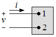

Details

An ideal basic circuit element has three attributes:
1. It has only two terminals, which are points of connection to other circuit components
2. It is described mathematically in terms of current and/or voltage
3. It cannot be subdivided into other elements

The word ideal is used to imply that a basic circuit element does not exist as a realizable physical component. However, ideal elements can be connected in order to model actual devices and systems. The word basic is used to imply that the circuit element cannot be further reduced or subdivided into other elements. Thus the basic circuit elements form the building blocks for constructing circuit models, but they themselves cannot be modeled with any other type of element.

The following figure is a representation of an ideal basic circuit element:


The box is blank because no commitment is being made at this time as to the type of circuit element it is. In the figure, the voltage across the terminals of the box is denoted by v, and the current in the circuit element is denoted by i. The polarity reference for the voltage is indicated by the plus and minus signs, and the reference direction for the currrent is shown by the arrow placed alongside the current. The interpretation of these references given positive or negative numerical values of v and i is summarized in the following table:

Positive ValueNegative Value
vVoltage drop from terminal 1 to terminal 2
or
Voltage rise from terminal 2 to terminal 1
Voltage rise from terminal 1 to terminal 2
or
Voltage drop from terminal 2 to terminal 1
iPositive charge flowing from terminal 1 to terminal 2
or
Negative charge flowing from terminal 2 to terminal 1
Positive charge flowing from terminal 2 to terminal 1
or
Negative charge flowing from terminal 1 to terminal 2

Note that algebraically the notion of positive charge flowing in one direction is equivalent to the notion of negative charge flowing in the opposite direction.