The case is now considered when the bending moment M is such that the normal stresses in the member remain below the yield strengthσY. This means that, for all practical purposes, the stresses in the member will remain below the proportional limit and the elastic limit as well. There will be no permanent deformation, and Hooke's law for uniaxial stress applies. Assuming the material to be homogeneous, and denoting by E its modulus of elasticity, the following results in the longitudinal x direction:
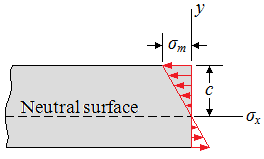
where σm denotes the maximum absolute value of the stress. This result shows that, in the elastic range, the normal stress varies linearly with the distance from the neutral surface as shown in Fig1.
This equation shows that the first moment of the cross section about its neutral axis must be zero. In other words, for a member subjected to pure bending, and as long as the stresses remain in the elastic range, the neutral axis passes through the centroid of the section.
Specifying that the z-axis should coincide with the neutral axis of the cross section, σx from Eq3 is substituted into Eq6:
(Eq7)
∫
(−y)
(
−
y
c
σm
)
dA = M
or:
(Eq8)
σm
c
∫
y 2dA = M
Recalling that in the case of pure bending the neutral axis passes through the centroid of the cross section, it is noted that I is the moment of inertia, or second moment, of the cross section with respect to a centroidal axis perpendicular to the plane of the couple M. Solving Eq8 for σm:
(Eq9)
σm =
Mc
I
Substituting for σm from Eq9 into Eq3, the normal stress σx at any distance y from the neutral axis is obtained:
(Eq10)
σm = −
My
I
Eq9 and Eq10 are called the elastic flexure formulas, and the normal stress σx caused by the bending or "flexing" of the member is often referred to as the flexural stress. It is verified that the stress is compressive (σx < 0) above the neutral axis (y > 0) when the bending moment M is positive, and tensile (σx > 0) when M is negative.
Returning to Eq9, it is noted that the ratio I / c depends only upon the geometry of the cross section. This ratio is called the elastic section modulus and is denoted by S. Then the elastic section modulus is:
(Eq11)
S =
I
c
Substituting S for I / c into Eq9:
(Eq12)
σm =
M
S
Since the maximum stress σm is inversely proportional to the elastic section modulus S, it is clear that beams should be designed with as large a value of S as practicable. For example, in the case of a wooden beam with a rectangular cross section of width b and depth h:
(Eq13)
S =
I
c
=
(1/12)bh3
h/2
= (1/6)bh2 = (1/6)Ah
where A is the cross-sectional area of the beam. This shows that, of two beams with the same cross-sectional area A as in Fig2, the beam with the larger depth h will have the larger section modulus and, thus, will be the more effective in resisting bending. However, large values of the ratio h/b could result in lateral instability of the beam.
In the case of structural steel, American standard beams (S-beams) and wide-flange beams (W-beams) are preferred to other shapes because a large portion of their cross section is located far from the neutral axis as shown in Fig3. Thus, for a given cross-sectional area and a given depth, their design provides large values of I and, consequently, of S. Values of the elastic section modulus of commonly manufactured beams can be obtained from tables listing the various geometric properties of such beams. To determine the maximum stress σm in a given section of a standard beam, the engineer needs only to read the value of the elastic section modulus S in a table, and divide the bending moment M in the section by S.
The deformation of the member caused by the bending moment M is measured by the curvature of the neutral surface. The curvature is defined as the reciprocal of the radius of curvature ρ, and can be obtained by solving Eq7 from the lesson Deformations in a Symmetric Member in Pure Bending for 1/ρ:
(Eq14)
1
ρ
=
εm
c
But, in the elastic range, the equation is εm = σm/E. Substituting for εm into Eq14, and recalling Eq9: