This might sound kind of abstract, but the normal or shear stresses that are observed within a member, regardless of application of axial or transverse loading, depend on the plane of examination. Imagine that for a given member, different planes can be sliced through it. This concept is of significant value and should be taken into consideration. For example, going down to the microstructure of metals, individual grains will be aligned at different angles, and the angles of the grain boundaries will be different, resulting in different combinations of normal and shear stress.
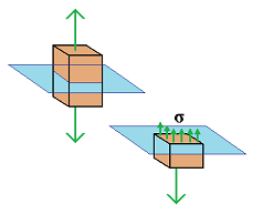
For example, visualize a member under axial loading, and the plane of interest is cut perpendicular to the forces through the member. This would mean that there is no shear stress, only normal stress to the plane. But if a plane is cut at an angle, then there will be a combinatioin of normal and shear stresses for the plane of consideration. Consider the following table:
parallel/perpendicular plane
oblique plane
axial loading
normal stress only
normal and shear stress
transverse loading
shear stress only
shear and normal stress
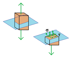
Consider a two-force member which is subjected to axial forces P and P'. A plane is cut through the member forming an angle θ with the normal plane. A free-body diagram of the portion of the member located to the left of the plane is constructed. The distributed forces acting on the cut surface are equivalent to the force P. The force P can then be resolved into componenents F and V, where F is the normal force that represents the normal stress multiplied by the area of the cut section and V is the tangential force that represents the shear stress multiplied by the area of the cut section. Then:
F = P cosθ
and:
V = P sinθ
The average values of the corresponding normal and shearing stresses are obtained by dividing, respectively, F and V by the area Aθ of the section:
(Eq1)
σ =
F
Aθ
and:
(Eq2)
τ =
V
Aθ
Substituting for F and V from Eq1 and Eq2 into Eq3 and Eq4, and observing from the figure that A0 = Aθ cosθ, or Aθ = A0/cosθ, where A0 denotes the area of a section perpendicular to the axis of the member, the following is obtained:
(Eq2)
σ =
P cosθ
A0 / cosθ
and:
(Eq2)
τ =
P sinθ
A0 / cosθ
or:
(Eq2)
σ =
P
A0
cos2θ
and:
(Eq2)
τ =
P
A0
sinθ cosθ
Note from Eq7 that the normal stress σ is maximum when θ = 0, i.e., when the plane of the section is perpendicular to the axis of the member, and that it approaches zero as θ approaches 90°. It is checked that the value of σ when θ = 0 is:
(Eq1)
σm =
P
A0
Eq8 shows that the shearing stressτ is zero for θ = 0 and θ = 90°, and that for θ = 45° it reaches its maximum value:
Related ▪ P - Normal and Shearing Stresses for an Axial Force